
Suppose a housing sits neatly over the board on the bench. The shop removes it, loads it a second time, and the connector catches the edge of its opening. That small change is the question worth bringing to a CNC machining service review. Which face located the housing? Where did the clamp touch it? Make those answers visible on the drawing, then check machining repeatability before signing off the setup.
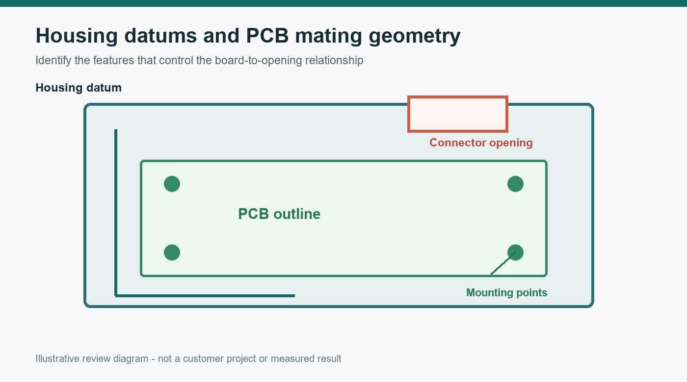
The drawing review needs to follow the actual assembly. Put the board supports, mounting holes, connector opening and cover face side by side. For the connector opening, identify the features that locate the board relative to the housing. Have the approving engineer mark those datum references on the drawing, including the revision used for the trial.
An accuracy request needs a place to measure from. A CNC machining service enquiry is more specific when it marks the critical dimension, its reference and the mating condition for acceptance. If the drawing simply asks for precision CNC machining, the supplier still needs to know which relationship matters. Add that information beside the feature being discussed.
Thin walls make CNC workholding worth a closer conversation. Mark where support and clamp contacts touch. Then measure the agreed feature while the housing is held and again after release. Different readings should prompt a review of the contacts and measurement conditions. Don't revise the model until engineering understands what changed.
The board files can help identify the geometry beside the housing. Gerber layers contain the board outline, and NC drill data provides the separate drilling input. Open that revision during the mounting discussion and have engineering mark the controlling dimensions. Keep the enclosure drawing beside it too; board exports leave the housing requirements to be defined. PCB electrical testing checks opens and shorts; passing those checks does not establish housing fit.
The populated board raises its own clearance questions. Pick-and-place coordinates and an SMT BOM belong in a PCB assembly submission, but they aren't a complete mechanical model. For the connector in our hypothetical review, add its drawing and the relevant component heights. Ask which geometry is still missing before accepting the clearance around the opening.
The combined housing and PCB assembly enquiry should explain which interfaces need review. At HTTPROTO, our services include mechanical prototypes, PCB and PCBA. Send the shared geometry together and ask us to confirm the process, material and inspection scope for your project. Those service categories give you an enquiry route; the proposed tolerance, finish and fixture still require their own discussion.
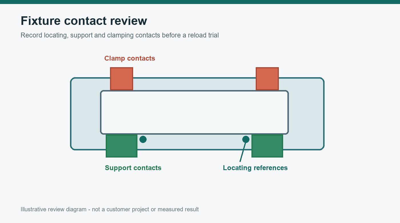
A CNC workholding plan should show how the housing is located, supported and clamped. In CNC fixture planning for prototype manufacturing, ask to see each contact on the sketch. Walk through the sequence: where does the housing seat, what is checked, and when is it clamped? Include any handling adjustments in the review.
Turning the housing creates another setup question. Which references can the operator still use, and how will the others transfer? Put the answer next to the dimension under review. Include that turn in the trial as well. A good first loading tells you little about the part after it has been repositioned.
Review CNC machining fixtures against the requirements of this housing:
· Identify the drawing and mating-part revisions.
· Mark locating, support and clamp contacts.
· Describe loading, adjustment and repositioning.
· Agree the checks and measurement conditions.
Replace these trial prompts with the actual drawing requirements before approving the plan.
Housing feature | Reference to identify | Question for the trial |
Board supports | Agreed base and mounting pattern | Does the board seat after reloading? |
Connector opening | Board position and connector geometry | Can the mating connector be installed? |
Cover face | Mating face and fastening condition | Does the cover fit after release? |
Thin wall | Support and clamp contacts | Do readings change when unclamped? |
A measurement without its holding condition can mislead the next reviewer. Was the housing clamped, resting free or attached to its mating parts? Record the answer beside the value. Use the condition agreed for acceptance when comparing results. If that condition changed, note it before treating the difference as a change in the part itself.
The reload trial should use an agreed number of loading cycles. Remove the housing, follow the same CNC workholding sequence and repeat the checks with the same mating parts. Record each critical dimension and its deviation from the drawing value, then compare the results with the specified tolerances. Watch for unrecorded adjustments, such as pushing a corner into place. Have engineering review the findings before accepting the method for prototype manufacturing.
A printed mock-up may help examine a limited access question earlier. Perhaps you want to see whether the proposed fixture blocks a fastener or the connector opening. Define that question before using 3D printing. Keep approval of the machined housing open: the different process and material still need consideration in its own trial.
The next review needs the reason behind a replacement model. Attach the observed interference, locating condition and proposed correction to the trial revision. Label findings from 3D printing as mock-up observations, so engineering knows what was examined. Rapid prototyping feedback is more useful when the reviewer can connect the changed feature to the question that prompted it.
CNC fixture planning ends with a drawing, loading sequence and reload record that can be reviewed together. Resolve unexplained adjustments and agree the measurement condition before accepting machining repeatability. Keep open findings visible when reviewing the next prototype manufacturing step, including the PCB assembly geometry and relevant rapid prototyping observations.
Discuss your housing setup with HTTPROTO by sending the model, drawing revision and mating-part details. Include the proposed locating method and the trial questions you want us to review.
Send the model, drawing revision and mating-part geometry. Mark the critical dimensions and references, then ask how the supplier proposes to load, support and measure the housing.
Each proposed contact needs an agreed purpose. Show its role on the sketch and have the responsible engineer review the arrangement before accepting it.
Record the agreed dimension under support and after release. Discuss the contacts and measurement conditions with engineering before deciding whether the model needs correction.
It can address a defined access or loading question. Identify that scope when reviewing 3D printing and rapid prototyping findings, and arrange the machining trial separately.
Record the interference with the part, mating and setup conditions. Have engineering review the proposed correction, then repeat the affected checks under the agreed conditions.



